Open Source FPGAs using Blackice Mx
This project is maintained by lawrie
| Prev | Up | Next |
Actuators
Servos

Servos are motors that are used to position things. They do not turn continuously, but can be set to a specific angle, in a range, typically, of between 180 and 270 degrees.
The angle is determined by the duty cycle of a PWM signal.
Servos cannot normally be driven by the BlackIce Mx power supply but require a separate power supply of at least 4.8 volts (for the small 9g servos).
A servo has three connections: Vcc, Gnd and the PWM signal.
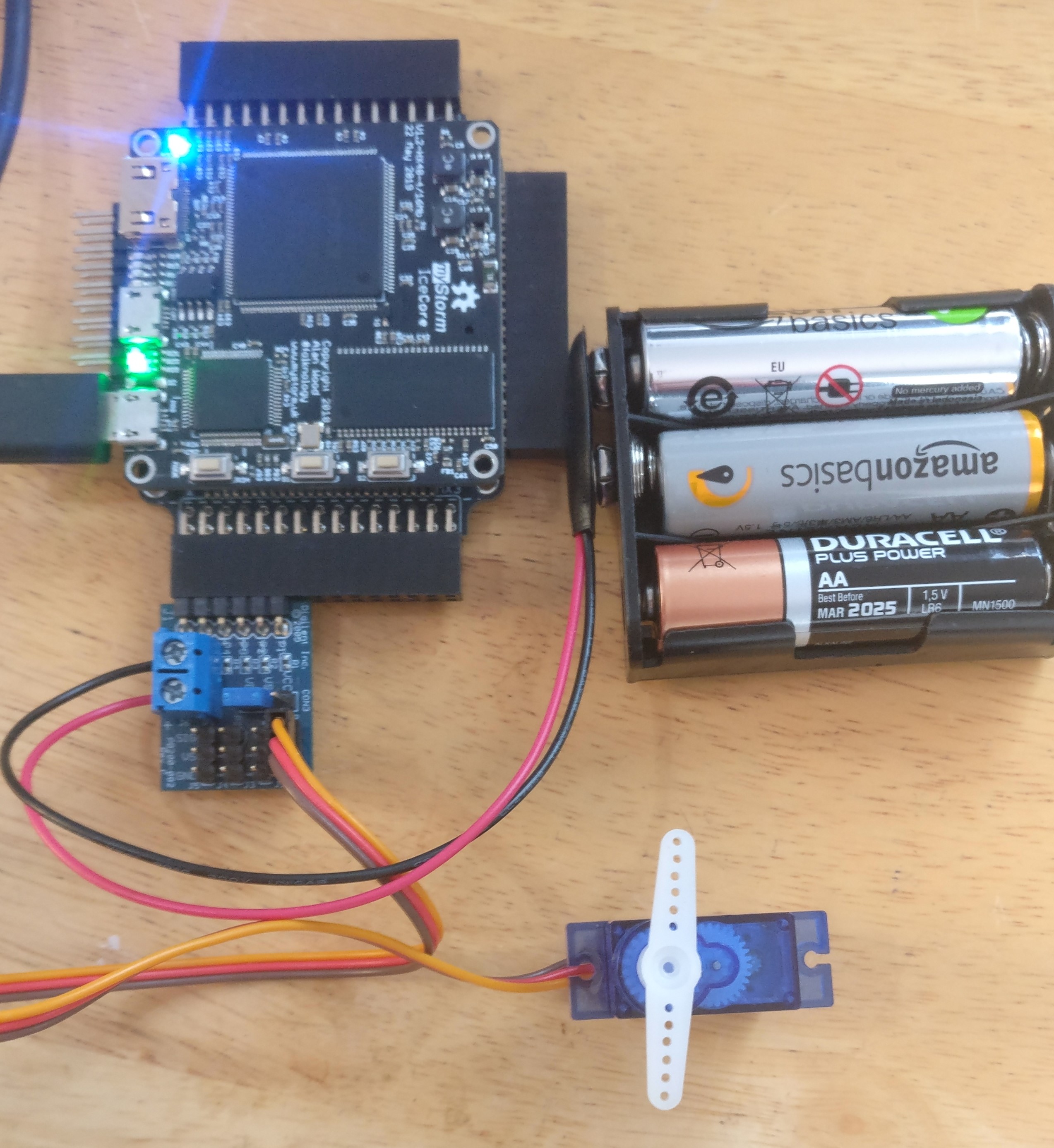
You can connect servos to BlackIce Mx using a Digilent CON3 R/C Servo Pmod, or just using breadboard wires.
Here is an example of using a servo with Blackice Mx using the Diglinet Pmod. It is based on the example from Chapter 7 of Simon Monk’s book.
Gear Motors
Gear motors are DC motors that turn continuously and have internal gears that determine how fast they turn in revs per minute (RPM). The speed of the motors is either quoted as the maximum RPM or the gear ratio used.
They usually have a + and a – connection and the voltage difference between these determines the direction of the motor and its speed. A PWM signal is usually applied at full positive or negative voltage rather than using an analog voltage.
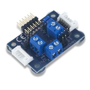
Gear motors need a motor driver such as an H-bridge to handle the power going to the motor. The Digilent DHB1 Dual H-bridge Pmod is suitable for this. It uses two pins to drive the motor: one digital signal to specify the direction and a PWM signal to specify the power.

Encoder Motors
Encoder motors are gear motors with encoders attached which measure the speed of rotation of the motor. The encoders can be optical or can use hall effect magnetic sensors. Two hall effect sensors are used at 90 degrees to each which count the turns of the DC motor before its gearing, so with high precision. The two sensors at 90 degrees allow the direction of the motor to be determined using a quadrature signal over two wires: quadA and quadB.
The encoder has its own (typically 3.3v power connection) and so has 4 wires. There are therefore 6 wires going to an encoder motor.
Encoder motors allow for precise control over stopping position and velocity, particularly when used in conjunction with a PID controller.
The Digilent DBH1 Pmod handles two encoder motors. If you use Digilent’s own motors, you can use the 6-pin JST connectors.
Encoder motors are driven the same as gear motors, but with the extra encoder input, which is the same as that used for quadrature rotary senstrs - see the Sensors chapter.
| Prev | Up | Next |