Open Source FPGAs using Blackice Mx
This project is maintained by lawrie
| Prev | Up | Next |
Programming the Built-in Hardware
This chapter describes how to use Verilog to access the built-in hardware on the BlackIce Mx board.
This built-in hardware covered consists of:
- The 4 user LEDS (two of which are shared with buttons)
- The two user buttons
- The UART to the STM32
Memory access including accessing the SDRAM, access to fkash memory, access to the SD card reader and the DSPI connection to the STM32 is covered in later chapters.
Development environment
All the projects are built using the open source icestorm tools: yosys, nextpnr-ice40, and icepack, and make files are used to build the bit streams to configure the Ice40 FPGA.
Instructions for setting the tools up for BlackIce Mx are here.
Each project has its own directory which contains the Verilog (.v) files, a .pcf file that maps port names onto physical pin numbers, and a Makefile of the form:
VERILOG_FILES = <list of Verilog files>
PCF_FILE = <pcf file>

include ../blackicemx.mk
Where blackicemx.mk is:
bin/toplevel.bin : bin/toplevel.asc
        icepack bin/toplevel.asc bin/toplevel.bin

bin/toplevel.json : ${VERILOG_FILES}
        mkdir -p bin
        yosys -q -p "synth_ice40 -json bin/toplevel.json" ${VERILOG_FILES}

bin/toplevel.asc : ${PCF_FILE} bin/toplevel.json
        nextpnr-ice40 --freq 64 --hx8k --package tq144:4k --json bin/toplevel.json --pcf ${PCF_FILE} --asc bin/toplevel.asc --opt-timing --placer heap

.PHONY: time
time: bin/toplevel.bin
        icetime -tmd hx8k bin/toplevel.asc

.PHONY: upload
upload : bin/toplevel.bin
        stty -F /dev/ttyACM0 raw
        cat bin/toplevel.bin >/dev/ttyACM0

.PHONY: clean
clean :
        rm -rf bin
LEDs
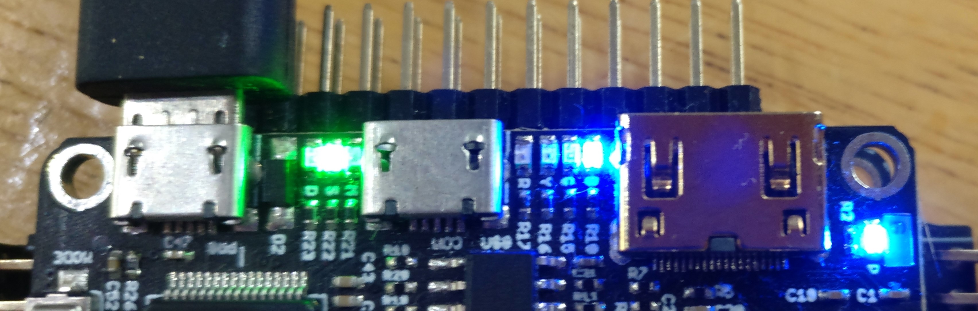
The BlackIce Mx board has 4 built in LEDs that are available to the FPGA:
- A blue LED, labelled B, with pin number 49;
- A green LED, labelled G, with pin number 52;
- A yellow LED, labelled Y, with pin number 55;
- A red LED, labelled R, with pin number 56.
Turn on an LED
You should create a development directory for running the examples in this book. Put the blackicemx.mk file given above in that directory.
Inside that development directory, make a directory called led, and in it add the following files.
You need a pcf file, led.pcf, to give the pin a name:
set_io blue_led 49
And a Verilog file, led.v:
module led(
  output blue_led
);

  assign blue_led = 0;

endmodule
And a Makefile:
VERILOG_FILES = led.v
PCF_FILE = led.pcf

include ../blackicemx.mk
Before building this example, you can open another terminal and in it, do:
stty -F /dev/ttyACM0 raw -echo
cat /dev/ttyACM0
This lets you see messages from the STM32 mystorm firmware when you upload bitstreams, but it is not normally necessary unless you are getting errors uploading the bitstream.
To run this example, type:
make upload
When configuration is successful the green STATUS (S) LED will be on and the red CDONE(D) LED will be off.
Your design should then run, and the blue LED should turn on. The other LEDs should all be off.
If the config fails for any reason, the green STATUS (S) LED will be off and red CDONE (D) LED will be on. The red CDONE (D) LED will be on while the upload is in progress.
The config will fail if /dev/tyyACM0 has not been set to raw, or if the bitstream (toplevel.bin) is invalid in some way. The cat command may hang if a failure occrs and you may have to unplug the Blackice Mx and plug it in again.
Another problem that can occur on Linux machine is that a program called modemmanager is running and accessing /dev/ttyACM0. If modemmanager is installed on your Linux machine, you should uninstall it, disable it, or use udev rules so that it ignores /dev/ttyACM0.
Note that in the Verilog above, the value assigned to blue_led to turn it on is 0, not 1. A value of 1 will turn it off. This is because of the way that the user LEDs are wired on the Blackice Mx iceCore board.
There are other ways in Verilog to set the LED, for example:
module led(
  output reg blue_led
);

  always @(*) blue_led = 0;

endmodule
Note that in that case, you need to declare blue_led as a reg not a wire to avoid a warning message, although this does not mean that flip-flops are used to store the value. This is just an alternative way of expressing combinatorial logic.
You can also use a clock and set the LED using sequential logic:
module led(
  input clk,
  output reg blue_led
);

  always @(posedge clk) blue_led = 0;

endmodule
In this case the reg does store a value and is implemented using flip-flops.
For this case you will need clk defined in your pcf file:
set_io blue_led 49
set_io clk 60
Pin 60 is the 25MHz system clock on the Blackice Mx.
If you use LEDs in your Verilog for debugging in can sometimes be easier to use combinatorial logic (the assign statement or always @(*) block) to set the LED, but if you want to set an LED when some condition has been triggered and then keep it set, the sequential logic style will be necessary.
An array of LEDs
You can address all 4 LEDs at once. Make a directory called led and in it add:
leds.pcf:
set_io leds[0] 49
set_io leds[1] 52
set_io leds[2] 55
set_io leds[3] 56
leds.v:
module leds(
  output [3:0] leds
);

  assign leds = 4’b0000;

endmodule
Makefile:
VERILOG_FILES = leds.v
PCF_FILE = leds.pcf

include ../blackicemx.mk
Buttons
The BlackIce Mx board has two built-in buttons available to the FPGA.
- Button 1, pin 49
- Button 2, pin 52
Note that button 1 is wired to the blue user LED and button 2 to the green user LED, so that those LEDs come on when you press the appropriate button.
If you are using pins 49 or 52 as buttons, you should declare them as input ports in your top level Verilog module, and you cannot write to the corresponding LEDs from verilog.
Light an LED when button pressed
You don’t need to use Verilog to set an LED when a button is pressed as the buttons are wired to the blue and green LEDS. But if you wanted to set one of the other two LEDs when the button is pressed, this is how you do it:
Make a directory called button_test and in it add:
button_test.pcf:
set_io yellow_led 55
set_io -pullup yes button1 49
button_test.v:
module button_test(
  output yellow_led,
  input button1
);

  assign yellow_led = button1;

endmodule
Makefile:
VERILOG_FILES = button_test.v
PCF_FILE = button_test.pcf

include ../blackicemx.mk
Note that -pullup yes is used in the pcf file for the button. Although the Blackice Mx has a pullup resistor on the button, because of the way the buttons are wired to the blue and green user LEDs, that resistor is not sufficient to get reliable signals from a button press, so the internal resistor needs to be enabled.
Note also that the button signal will be high by default and low when the button is pressed, and that the user LEDs are set on when their output signal is low, and off when it is high. So no negation is needed when setting the LED signal from the button signal.
If you need more buttons for your project, you can buy the Digilent Pmod BTN, which has 4 buttons.
Debouncing
Accessing buttons as in the way given by the previous example is not recommended as a button takes a while to stabilise when it is pressed and if this is not programmed for, a single button press can appear as multiple presses.
Coping with this behaviour is known as debouncing the button.
There is an article on this at fpga4fun.com.
To see the problem, lets implement a simple button press module and use 3 LEDs as a counter:
Make a directory called bounce and add:
bounce.pcf
set_io leds[0] 52
set_io leds[1] 55
set_io leds[2] 56

set_io -pullup yes button 49
bounce.v
module bounce(
  input button,
  output [2:0] leds
);

  reg [2;0] led_counter;
  assign leds = ~led_counter;

  always @(negedge button) led_counter <= led_counter + 1;

endmodule
Makefile:
VERILOG_FILES = bounce.v
PCF_FILE = bounce.pcf

include ../blackicemx.mk
We use negedge as the button is pulled low when pressed.
Build and upload in the normal way and you should see the LED counter increasing by more than one per press.
To fix this, we will use the debouncer from fpga4fun.com.
So, create a directory called debounce and add:
debounce.pcf:
set_io clk 60

set_io leds[0] 52
set_io leds[1] 55
set_io leds[2] 56

set_io -pullup yes button 49
Then add the debouncer from fpga4fun.com:
PushButton_Debouncer.v:
module PushButton_Debouncer(
	input clk,
	input PB,  // "PB" is the glitchy, asynchronous to clk, active low push-button signal

	// from which we make three outputs, all synchronous to the clock
	output reg PB_state,  // 1 as long as the push-button is active (down)
	output PB_down,  // 1 for one clock cycle when the push-button goes down (i.e. just pushed)
	output PB_up   // 1 for one clock cycle when the push-button goes up (i.e. just released)
);

	// First use two flip-flops to synchronize the PB signal the "clk" clock domain
	reg PB_sync_0;  always @(posedge clk) PB_sync_0 <= ~PB;  // invert PB to make PB_sync_0 active high
	reg PB_sync_1;  always @(posedge clk) PB_sync_1 <= PB_sync_0;

	// Next declare a 16-bits counter
	reg [15:0] PB_cnt;

	// When the push-button is pushed or released, we increment the counter
	// The counter has to be maxed out before we decide that the push-button state has changed

	wire PB_idle = (PB_state==PB_sync_1);
	wire PB_cnt_max = &PB_cnt;	// true when all bits of PB_cnt are 1's

	always @(posedge clk)
	if(PB_idle)
		PB_cnt <= 0;  // nothing's going on
	else
	begin
		PB_cnt <= PB_cnt + 16'd1;  // something's going on, increment the counter
		if(PB_cnt_max) PB_state <= ~PB_state;  // if the counter is maxed out, PB changed!
	end

	assign PB_down = ~PB_idle & PB_cnt_max & ~PB_state;
	assign PB_up   = ~PB_idle & PB_cnt_max &  PB_state;
endmodule
Then, to test it add debounce.v:
module debounce(
	input clk,
	input button,
	output [2:0] leds
);

	reg PB_state, PB_down, PB_up;

	PushButton_Debouncer pdb (
		.clk(clk),.PB(button), .PB_state(PB_state),
		.PB_down(PB_down), .PB_up(PB_up)
	);

	reg [2:0] led_count;
	assign leds = ~led_count;

	always @(posedge clk) if (PB_down) led_count <= led_count + 1;

endmodule
and a Makefile:
VERILOG_FILES = debounce.v PushButton_Debouncer.v
PCF_FILE = debounce.pcf

include ../blackicemx.mk
When you make and run this you should see the LED counter increase by 1 for each button press.
PWM
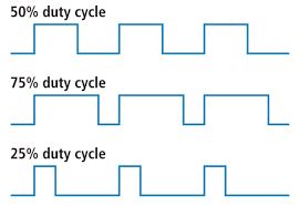
Pulse width modulation (PWM) is a technique to vary the power output on a digital pin by turning it on and off in pulses. A square wave of a specific frequency is sent to the pin and the length of time it is set high for each period is called the duty cycle.
This technique can be used to specify the position of servo motors, the speed of gear motors, or the volume of audio (see 1-bit DAC below). It is a sort of digital equivalent of specifying the voltage level for an analog output, and can sometimes be used for the same purpose, avoiding the need for digital to analog converters.
Here we will use it to set the brightness of a built-in LED.
Make a directory called LEDglow and in it add:
LEDglow.pcf
set_io LED 49
set_io clk 60
LEDglow.v
module LEDglow(clk, LED);
	input clk;
	output LED;

	reg [27:0] cnt;
	always @(posedge clk) cnt<=cnt+1;

	wire [3:0] PWM_input = cnt[27] ? cnt[26:23] : ~cnt[26:23];
	reg [4:0] PWM;
	always @(posedge clk) PWM <= PWM[3:0]+PWM_input;

	assign LED = ~PWM[4];
endmodule
Makefile:
VERILOG_FILES = LEDglow.v
PCF_FILE = LEDglow.pcf

include ../blackicemx.mk
Then run the Makefile in the normal way. You will see the blue LED glowing.
UART
The IceCore github site has a set of example programs including a comprehensive example on the use of the uart.
The uart is connected to pins 62 (TX) and 61 (RX) of the Ice40.
The line_echo example reads from the uart and echoes back what it reads at 115200 baud.
| Prev | Up | Next |