Open Source FPGAs using Blackice Mx
This project is maintained by lawrie
| Prev | Up | Next |
Output Devices
LEDs
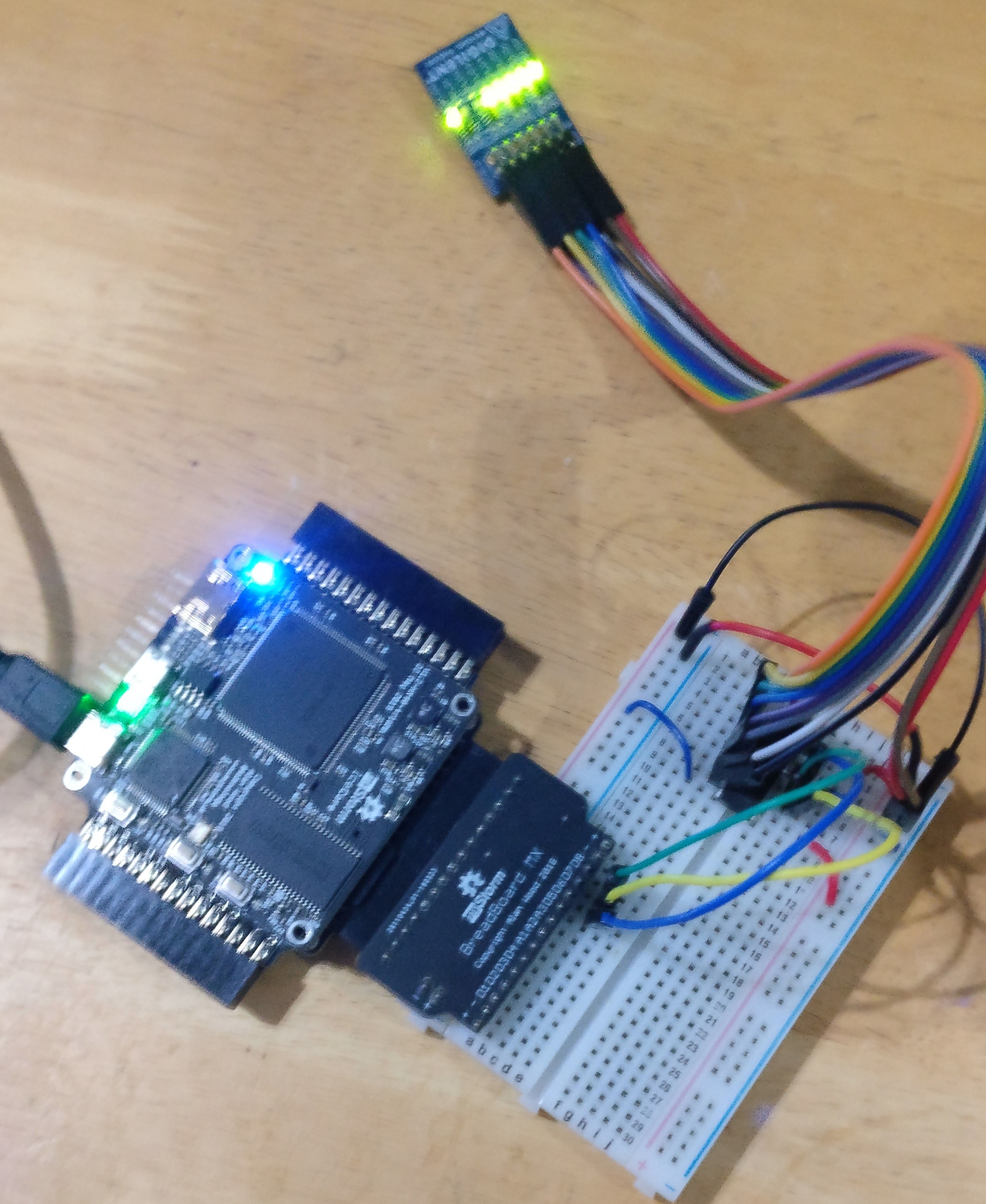
If you need more LEDs than the 4 built-in ones, you can buy an LED Pmod. The Digilent Pmod8LD has 8 leds, or you can make your own. An 8-LED Pmod is useful for simple diagnostics, displaying the value of a byte as a bit pattern.

Here is an example with the Pmod connected to Pmod 3 / 4.
Make a directory called leds8 and add:
leds.pcf
set_io clk 60

set_io leds[0] 34
set_io leds[1] 33
set_io leds[2] 29
set_io leds[3] 28
set_io leds[4] 38
set_io leds[5] 37
set_io leds[6] 32
set_io leds[7] 31
leds.v
module leds(
  input clk,
  output reg [7:0] leds
);

  reg [19:0] counter;

  always @(posedge clk) begin
    counter <= counter + 1;
    if (counter == 0) leds <= leds + 1;
  end

endmodule
Makefile
VERILOG_FILES = leds.v
PCF_FILE = leds.pcf

include ../blackicemx.mk
RGB LEDs

RGB LEDS have three connections for red, green and blue, and can display combination of those colours, such as cyan, tallow and magenta.
A simple program to set the RGB according to three slider switches is as follows. Connect an RGB LED to pins 1, 2 and 3 of Pmod 11 (top row). A breadboard adapter from the myStorm Pmod hackers kit can be used to do this. You need resistors on each of the RGB pins to limit the current.
Create a directory called rgbled and add:
rgbled.pcf:
set_io rgb[0] 34
set_io rgb[1] 33
set_io rgb[2] 29

set_io switch[0] 142
set_io switch[1] 141
set_io switch[2] 136
rgbled.v:
module rgbled(
	input [2:0] switch,
	output [2:0] rgb
);

	assign rgb = switch;

endmodule
Makefile:
VERILOG_FILES = rgbled.v
PCF_FILE = rgbled.pcf

include ../blackicemx.mk
You can then use the first three dip switches on the board to set the colour of the RGB LED.
74HC595 shift register
You can drive 8 or more LEDs with just 3 pins using am 74HC595 shift register chip.
Here is an example.
Seven segment displays
3-digit MixMod
The myStorm 7-segment MixMod has three digits with optional decimal points. It also has 4 dip switches and an optional header for reading some digital and analog signals from the MixMod.
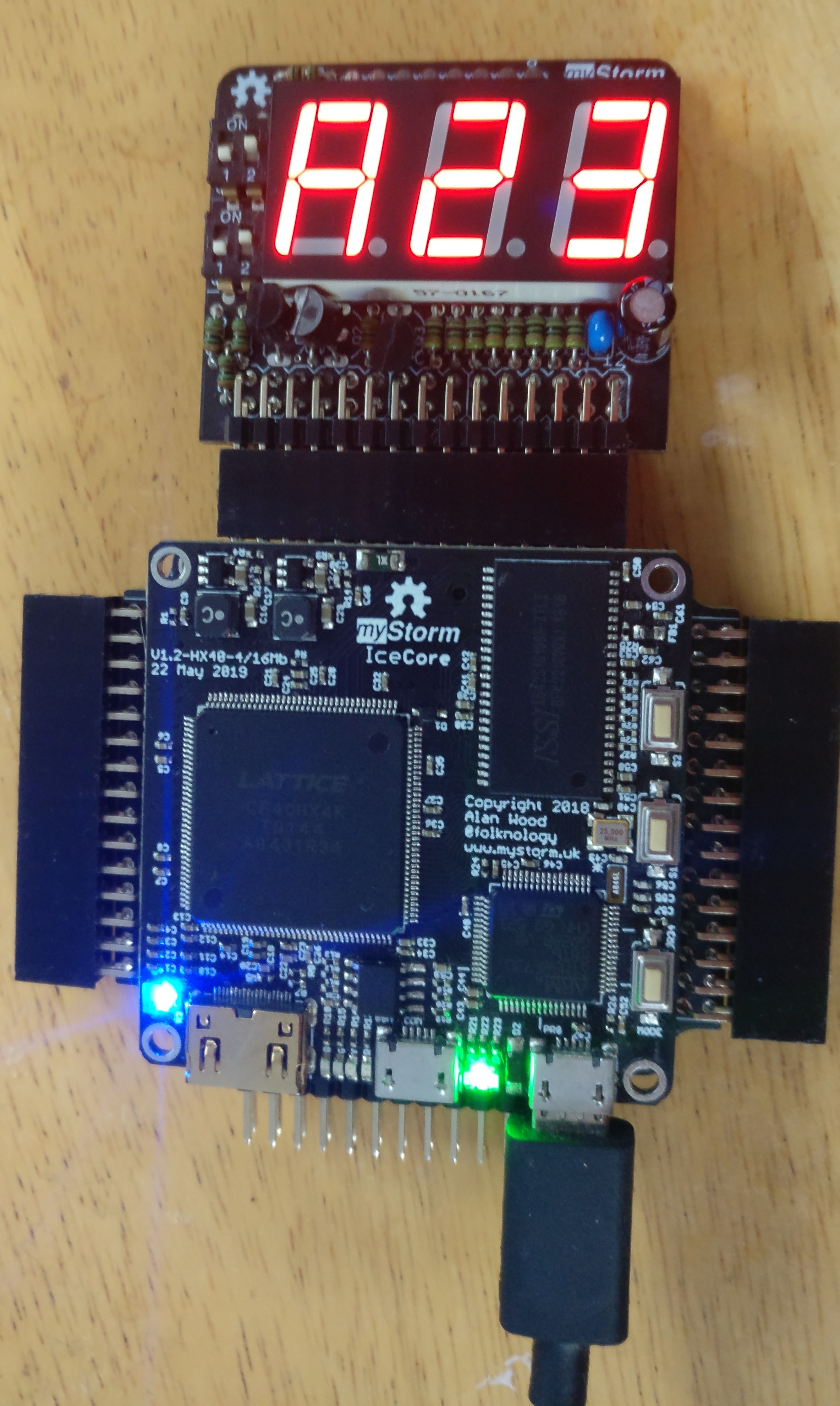
Seven segment displays are useful for diagnostics and as a simple user interface. They can display decimal or hex numbers.
Seven segment displays usually have a pin for each segment and another for the dot that optionally separates digits. The digits themselves are usually multiplexed, with a selector pin for each digit. Each digit must be selected, and its segments activated about one thousand times a second.
This example displays three hex digits, the first of which is the bit pattern from the switches:
This example
The hex27seg.v module converts a hex digit to the output pins to set the relevant segments:
module h27seg (
    input wire [3:0] hex,
    output reg [6:0] s7
    );

    always @(*)
        case (hex)
            // Segments - gfedcba
            4'h0: s7 = 7'b1000000;
            4'h1: s7 = 7'b1111001;
            4'h2: s7 = 7'b0100100;
            4'h3: s7 = 7'b0110000;
            4'h4: s7 = 7'b0011001;
            4'h5: s7 = 7'b0010010;
            4'h6: s7 = 7'b0000010;
            4'h7: s7 = 7'b1111000;
            4'h8: s7 = 7'b0000000;
            4'h9: s7 = 7'b0010000;
            4'hA: s7 = 7'b0001000;
            4'hB: s7 = 7'b0000011;
            4'hC: s7 = 7'b1000110;
            4'hD: s7 = 7'b0100001;
            4'hE: s7 = 7'b0000110;
            4'hF: s7 = 7'b0001110;
            default: s7 = 7'b1111111;
        endcase

endmodule
The 7seg_display.v module periodically displays each digit before they fade:
module seven_seg_display (
	input clk,
	output reg [2:0] ca,
	);

	initial begin
		ca = 3'b110;
	end

	reg [17:0] count;

	always @(posedge clk) begin
    	count <= count + 1;
		if(count[17]) begin
			count <= 0;
			ca <= {ca[1:0], ca[2]};
		end
	end

endmodule
And here is the top level 7seg.v module:
module chip(
  input clk,
  output [2:0] ca,
  output [7:0] seg,
  input  [3:0] d
);

 wire [11:0] val = 'h123;
 wire [3:0] dig = (ca == 'b011 ? d : ca == 'b101 ? val[7:4] : val[3:0]);
 assign seg[7] = 1;

 h27seg hex (
   .hex(dig),
   .s7(seg[6:0])
 );

 seven_seg_display seg7 (
   .clk(clk),
   .ca(ca)
 );

endmodule
7seg_display.pcf:
set_io clk 60

#set_io led[0] 49 # B81/GBin5 L0 Blue led / S2 button
#set_io led[1] 52 # B82/GBin4 L1 Green led / S1 button
#set_io led[2] 55 # B91 L3 Yellow led
#set_io led[3] 56 # B94 cs Red led

set_io seg[0] 3  # a
set_io seg[1] 4  # b
set_io seg[2] 144  # c
set_io seg[3] 143  # d
set_io seg[4] 1  # e
set_io seg[5] 8  # f
set_io seg[6] 7  # g
set_io seg[7] 2  # dp

set_io ca[0] 135  # ca0
set_io ca[1] 139 # ca1
set_io ca[2] 138  # ca2

set_io d[0] 142
set_io d[1] 141
set_io d[2] 136
set_io d[3] 137
and the Makefile:
VERILOG_FILES = 7seg.v 7seg_display.v hex27seg.v
PCF_FILE = 7seg_display.pcf

include ../blackicemx.mk
2-Digit Digilent Pmod
Digilent make the PmodSSD, a two-digit 7-segment display Pmod.
This can be driven in a simlar way, except that there are just two digits, no decimal points and a single pin is used to select which digit to display.
VGA output

Driving a VGA monitor required a Pmod such as the Digilent PmodVGA. It uses 4-bits for each of the red, green and blue colours.
We will concentrate on supporting the standard 640 x 480 pixel resolution, but it is possible to support higher frequencies.
A clock for 640 x 480 VGA can be produced in a few different ways. Using a pre-scaler to divide the 100 Mhz clock by 3 to produce a 33.3Mhz clock works, but is slightly out of spec. Using a pre-scaler to produce a 25Mhz clock works, but not all VGA monitors support that frequency. Using a PLL to produce a 31.5 Mhz clock is the most accurate way.
We will use the pong example from the fpgafun web site to demonstrate VGA output. The only change to the code from the fpgafun.com is the addition of the 31.5Mhz clock using a PLL. This means that we are not using the full 4-bit VGA output. Instead we map the single R, G and B signals used by the code to the pin corresponding to the most significant bit of the 4-bits used by the Digilent Pmod.
This example needs a Digilent VGA Pmod in Pmods 7/8/9/10 and a rotary encoder for moving the paddle in Pmod3, pins 1 and 2 (top row). Rotary sensors are explained in the Sensors chapter below.
Make a directory called pong, and add:
pong.v
// Pong VGA game
// (c) fpga4fun.com

module pong(clk25, vga_h_sync, vga_v_sync, vga_R, vga_G, vga_B, quadA, quadB);
input clk125;
output vga_h_sync, vga_v_sync, vga_R, vga_G, vga_B;
input quadA, quadB;

wire inDisplayArea;
wire [9:0] CounterX;
wire [8:0] CounterY;
wire clk = clk25;

hvsync_generator syncgen(.clk(clk), .vga_h_sync(vga_h_sync), .vga_v_sync(vga_v_sync),
	.inDisplayArea(inDisplayArea), .CounterX(CounterX), .CounterY(CounterY));

/////////////////////////////////////////////////////////////////
reg [8:0] PaddlePosition;
reg [2:0] quadAr, quadBr;
always @(posedge clk) quadAr <= {quadAr[1:0], quadA};
always @(posedge clk) quadBr <= {quadBr[1:0], quadB};

always @(posedge clk)
if(quadAr[2] ^ quadAr[1] ^ quadBr[2] ^ quadBr[1])
begin
	if(quadAr[2] ^ quadBr[1])
	begin
		if(~&PaddlePosition)        // make sure the value doesn't overflow
			PaddlePosition <= PaddlePosition + 1;
	end
	else
	begin
		if(|PaddlePosition)        // make sure the value doesn't underflow
			PaddlePosition <= PaddlePosition - 1;
	end
end

/////////////////////////////////////////////////////////////////
reg [9:0] ballX;
reg [8:0] ballY;
reg ball_inX, ball_inY;

always @(posedge clk)
if(ball_inX==0) ball_inX <= (CounterX==ballX) & ball_inY; else ball_inX <= !(CounterX==ballX+16);

always @(posedge clk)
if(ball_inY==0) ball_inY <= (CounterY==ballY); else ball_inY <= !(CounterY==ballY+16);

wire ball = ball_inX & ball_inY;

/////////////////////////////////////////////////////////////////
wire border = (CounterX[9:3]==0) || (CounterX[9:3]==79) || (CounterY[8:3]==0) || (CounterY[8:3]==59);
wire paddle = (CounterX>=PaddlePosition+8) && (CounterX<=PaddlePosition+120) && (CounterY[8:4]==27);
wire BouncingObject = border | paddle; // active if the border or paddle is redrawing itself

reg ResetCollision;
always @(posedge clk) ResetCollision <= (CounterY==500) & (CounterX==0);  // active only once for every video frame

reg CollisionX1, CollisionX2, CollisionY1, CollisionY2;
always @(posedge clk) if(ResetCollision) CollisionX1<=0; else if(BouncingObject & (CounterX==ballX   ) & (CounterY==ballY+ 8)) CollisionX1<=1;
always @(posedge clk) if(ResetCollision) CollisionX2<=0; else if(BouncingObject & (CounterX==ballX+16) & (CounterY==ballY+ 8)) CollisionX2<=1;
always @(posedge clk) if(ResetCollision) CollisionY1<=0; else if(BouncingObject & (CounterX==ballX+ 8) & (CounterY==ballY   )) CollisionY1<=1;
always @(posedge clk) if(ResetCollision) CollisionY2<=0; else if(BouncingObject & (CounterX==ballX+ 8) & (CounterY==ballY+16)) CollisionY2<=1;

/////////////////////////////////////////////////////////////////
wire UpdateBallPosition = ResetCollision;  // update the ball position at the same time that we reset the collision detectors

reg ball_dirX, ball_dirY;
always @(posedge clk)
if(UpdateBallPosition)
begin
	if(~(CollisionX1 & CollisionX2))        // if collision on both X-sides, don't move in the X direction
	begin
		ballX <= ballX + (ball_dirX ? -1 : 1);
		if(CollisionX2) ball_dirX <= 1; else if(CollisionX1) ball_dirX <= 0;
	end

	if(~(CollisionY1 & CollisionY2))        // if collision on both Y-sides, don't move in the Y direction
	begin
		ballY <= ballY + (ball_dirY ? -1 : 1);
		if(CollisionY2) ball_dirY <= 1; else if(CollisionY1) ball_dirY <= 0;
	end
end

/////////////////////////////////////////////////////////////////
wire R = BouncingObject | ball | (CounterX[3] ^ CounterY[3]);
wire G = BouncingObject | ball;
wire B = BouncingObject | ball;

reg vga_R, vga_G, vga_B;
always @(posedge clk)
begin
	vga_R <= R & inDisplayArea;
	vga_G <= G & inDisplayArea;
	vga_B <= B & inDisplayArea;
end

endmodule
Get hvsync_generator.v from the fpga.fun site.
pong.pcf
set_io   clk25       60
set_io   vga_h_sync  1
set_io   vga_v_sync  2
set_io   vga_R       139
set_io   vga_G       4
set_io   vga_B       135
set_io   quadA       21
set_io   quadB       22
And a Makefile:
VERILOG_FILES = pong.v hsync_generator.v
PCF_FILE = pong.pcf

include ../blackicemx.mk
Use the rotary encoder to move the paddle.
Neopixels
![]()
WS2811, WS2812 and WS2812B neopixel strips use PWM signals over a single wire to switch and set the colour of each pixel in a strip. Longer strips need a separate power supply.
Here is an example of driving a short 8 neopixel strip.
OLED displays
I2C OLED displays
Some of the cheaper OLED displays are driven by I2C. There are cheap 4-pin modules available on ebay and elsewhere that can be plugged in to a Pmod header via a simple homemade adapter or even directly into the Pmod header (or via a connecting cable) if VCC and GND are in the correct position. An I2C master module, mod_i2c_master is available in BlackSoC, with an example program. Some versions of the module use two colours, but they are fixed and not variable by software. Often the top lines of that display use yellow text and the other lines blue.
It is harder to access i2c oled displays and other i2c devices without a soft processor as they have complex sequences of commands for initialisation and writing data. However it is not too hard to set up a ROM with the appropriate initialisation commands.
SPI OLED displays

OLED displays such sssd1306, ssd1351 etc. Are driven either by the SPI or I2C protocol.
Icosoc has an implementation of an SPI master in mod_spi which is also in BlackSoC.
The OLED displays use a variant of SPI that is output only and so has no MISO pin, and which has an extra pin (DC) to distinguish between commands and data. They also have a reset pin. To cope with this a new BlackSoC module, mod_spi_oled has been produced.
There are BlackSoC examples for a variety of monochrome and RGB SPI OLED displays: the ssd1306 or sh1106, the ssd1331 and the ssd1335.
LCD Displays
LCD Text Displays
Parallel-connected text LCDs

The fpgafun site shows how to drive these displays, and here is the example, modified to run on the BlackIce Mx. You can send commands and data to it from the command line e.g.
echo -n -e "\x00\x38" >/dev/ttyACM0
echo -n -e "\x00\x0F" >/dev/ttyACM0
echo -n -e "\x00\x01" >/dev/ttyACM0
echo -n "Hello World!" >/dev/ttyACM0
| Prev | Up | Next |