Open Source FPGAs using Blackice Mx
This project is maintained by lawrie
| Prev | Up | Next |
Simulation
Simulation is a useful technique to verify and debug your Verilog designs.
There are two common open source tools that are used for simulation: Icarus Verilog (iverilog) and Verilator.
With Icarus Verilog you write a test bench for the component that you want to test in System Verilog. System Verilog has many features for testing that are not synthesizable and connot be used in standard Verilog.
Verilator is a more powerful tool that generates C++ from your Verilog code. You normally write a testbench in C++ to test your Verilog modules, and do not usually need to write a System Verilog testbench. Verilator has interactive and graphical simulators for a lot of components.
Icarus Verilog
We will write a testbench for the txuart module in the line-echo IceCore example.
This testbench uses the uart transmitter to send two characters “H” and “e” and to write a .vcd file that can then be looked at with gtkwave to check that the waveform on the output pin is correct.
Here is the testbench, tb.v:
timescale 1ns/100ps

module tb();
        initial begin
                $dumpfile("waves.vcd");
                $dumpvars(0);
        end

        reg clk;

        initial begin
                clk = 1'b0;
        end

        always begin
                #20 clk = !clk;
        end

        reg       i_wr;
        wire      o_busy;
        reg [7:0] i_data;
        wire      o_uart_tx;

        txuart #(.CLOCKS_PER_BAUD(217)) u_txuart (
                .i_clk (clk),
                .i_wr(i_wr),
                .i_data(i_data),
                .o_busy(o_busy),
                .o_uart_tx(o_uart_tx)
        );

        initial begin
                i_wr            = 1'b0;
                repeat(10) @(posedge clk);

                @(posedge clk);
                i_wr            = 1'b1;
                i_data          = "H";

                @(negedge o_busy);
                @(posedge clk);

                i_data          = "e";

                @(negedge o_busy);
                @(posedge clk);

                i_wr            = 1'b0;

                repeat(10) @(posedge clk);

                $finish;
        end
endmodule
The testbench starts by specifying the output waves.vcd file using $dumpfile and specifies that all variables should be written to that file by the call to $dumpvars.
It then defines a clock that initially zero and completes a cycle in 40ns, i.e. runs at 25Mhz.
It then instantiates txuart and defines registers for its input signals and wires for its output ones.
The test code starts with i_wr=0 and then sends a character by setting i_wr=1 and i_data=”H”. It waits for o_busy to go to zero, for the character to have been sent, and then sets i_data=”e” to send the next character (leaving i_wr=1). When this has been sent, it sets i_wr=0 to prevent further transmission and after a few clock cycles, finishes (using $finish).
You can compile tb.v by doing:
iverilog -o tb tb.v txuart.v
and then run it, by:
./tb
You can then view the wave file by:
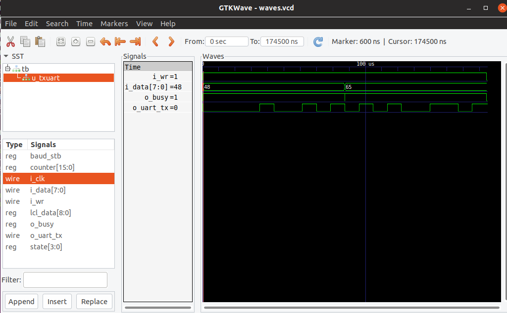
gtkwave waves.vcd
This is the relevant part of the wave file, as shown by gtkwave. You can confitm that the o_uart_tx signal is correct.
Verilator
Here is an example of the use of Verilator taken from Dan Gisselquist’s ZipCPU tutorial.
You will need to install Verilator, which on Debian variants of Linux can be done by sudo apt-get install verilator, but if you plan to use SpinalHDL, a more recent version may be needed - see the SpinalHDL chapter.
The simple Verilog design (thruwire.v) from the ZipCPU tutorial is:
`default_nettype 	none

module	thruwire(i_sw, o_led);
	input	wire i_sw;
	output	wire o_led;

	assign	o_led=i_sw;
endmodule
The Makefile for this is:
VERILOG_FILES = thruwire.v
PCF_FILE = thruwire.pcf
CPP_FILES = thruwire.cpp
VERILATOR_HOME = /usr/local/share/verilator

include ../blackicemx.mk

sim: ${VERILOG_FILES} ${CPP_FILES}
	verilator  -Wall -cc  ${VERILOG_FILES}
	(cd obj_dir; make -f Vthruwire.mk)
	g++ -I ${VERILATOR_HOME}/include -I obj_dir/ ${VERILATOR_HOME}/include/verilated.cpp ${CPP_FILES}  obj_dir/Vthruwire__ALL.a -o tb
	./tb

clean:
	rm -rf bin obj_dir tb
The pcf file is:
set_io -pullup yes i_sw 49
set_io o_led 56
All these files are part of this example.
To synthesize that design and run it on the Blackice Mx, do make upload. When you press button 1, you should see both the blue and red LEDs come on. The blue led is wired to the button and thruwire Verilog module causes the red LED to come on when the button is pressed.
To run the verilator simulation, you need the thruwire.cpp file:
#include <stdio.h>
#include <stdlib.h>
#include "Vthruwire.h"
#include "verilated.h"

int main(int argc, char**argv) {
	// Call  commandArgs  first!
	Verilated::commandArgs(argc, argv);
	//  Instantiate  our  design
	Vthruwire *tb = new Vthruwire;

	for(int k=0; k<20; k++) {
		// We’ll set  the  switch  input
		// to the  LSB of our  counter
		tb->i_sw = k&1;
		tb->eval();

		// Now  let’s print  our  results
		printf("k = %2d, ", k);
		printf("sw = %d, ", tb->i_sw);
		printf("led = %d\n", tb->o_led);
	}
}
You then do make sim to build and run the simulation and you should see this output:
k =  0, sw = 0, led = 0
k =  1, sw = 1, led = 1
k =  2, sw = 0, led = 0
k =  3, sw = 1, led = 1
k =  4, sw = 0, led = 0
k =  5, sw = 1, led = 1
k =  6, sw = 0, led = 0
k =  7, sw = 1, led = 1
k =  8, sw = 0, led = 0
k =  9, sw = 1, led = 1
k = 10, sw = 0, led = 0
k = 11, sw = 1, led = 1
k = 12, sw = 0, led = 0
k = 13, sw = 1, led = 1
k = 14, sw = 0, led = 0
k = 15, sw = 1, led = 1
k = 16, sw = 0, led = 0
k = 17, sw = 1, led = 1
k = 18, sw = 0, led = 0
k = 19, sw = 1, led = 1
There is a lot more information in the ZipCPU tutorial.
In particular, the design above is a simple combinatorial one that does not use a clock. Most designs use a clock and your cpp will need a function such as tick to advance the clock each cycle and do an evaluation to determine the state of all the variable after the clock has ticked.
If your clock is called i_clk and your top-level Verilog module is called top, your tick function can be defined as:
void tick (Vtop *tb) {
        // The following eval() looks
        // redundant ... many of hours
        // of debugging reveal its not
        tb->eval();
        tb->i_clk = 1;
        tb->eval();
        tb->i_clk = 0;
        tb->eval();
}
If you want to produce a wave file for analysis by gtkwave, you include a code such as:
        // Generate a trace
        Verilated::traceEverOn(true);
        VerilatedVcdC *tfp = new VerilatedVcdC;
        tb >trace(tfp , 99);
        tfp->open("wave.vcd");
}
| Prev | Up | Next |